Bevel Gear
Bevel Gear
Bevel Gear Design
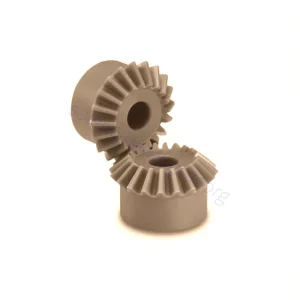
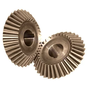
Around the perimeter of the disk’s face are the teeth – elevated segments of equal length that protrude in the Z-axis and are shaped like straight lines or waves.
Depending on the gear’s configuration, the teeth may be higher toward the middle and lower toward the gear’s perimeter; if viewed from the side, the gear would look like a ridged, truncated cone.
A bevel gear’s axis extends from its middle in the Z-axis. That axis intersects with the axis of at least one other bevel gear, and it is this axial intersection that distinguishes bevel gears from different gear varieties.
Bevel gears are industrial gears that are characterized by gear axis intersection. A gear is a machined wheel, the circumference or face of which features specially shaped teeth. When those teeth interact with similarly shaped teeth on other gears, torque can be transferred between the two gears as they turn.
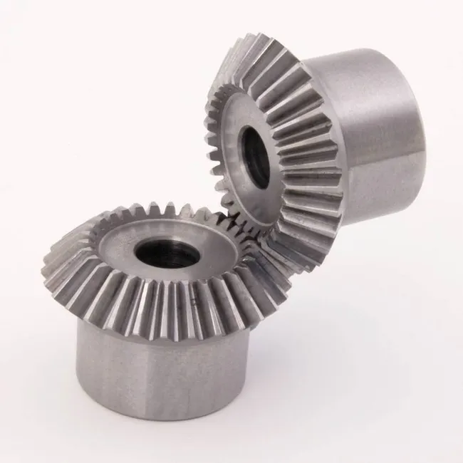
What is a Straight Bevel Gears?
advantage
- Axial force is only generated in the direction of the opposing gears
- Don’t worry about left-hand and right-hand gear pairings
Disadvantage
- Tooth surface grinding is not possible, so high-precision gears cannot be produced
- Less strength than spiral bevel gears


Materials Used in Bevel Gears
Types of Bevel Gears
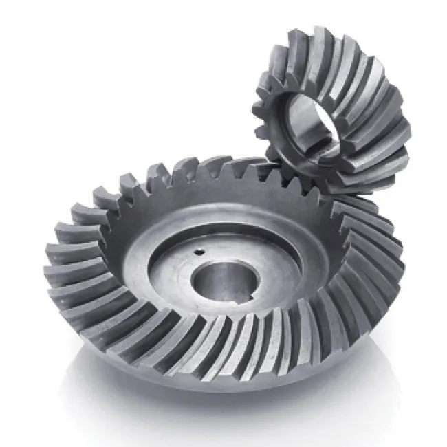
Spiral Bevel Gears


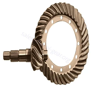
Hypoid Bevel Gears
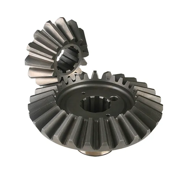
Miter Bevel Gears


Bevel Gears
Main Applications of Bevel Gears
(1) Bevel gears are employed in differential drives, which can transfer energy to two axles rotating at different velocities, such as those on a cornering automobile.
(2) Bevel gears are used as the basic function for a hand drill. As the handle of the drill is rotated in a vertical form, the bevel gears modify the spinning of the chuck to a horizontal motion.
(3) The gears in a bevel gear planer allow for minor regulation during assembly and permit some displacement based on the deflection under operating powers without concentrating the force on the end part of the tooth.
(4) Spiral bevel gears are essential parts of rotorcraft drive arrangements.
Products Center
-

China Factory Best Cheap Hypoid Bevel Gear
-
Custom Injection Molding Wear Resistant Plastic Bevel Gear
-
Customized High Precision Spiral Bevel Gears
-
Drawing And Sample Custom Special Straight Bevel Gears
-
Stainless Steel Forging Miter Bevel Gears
-
Teeth Hardened Ground Zerol Bevel Gears for Vehicle Differential
The Advantages of Bevel Gears